![]()
CAN bus display
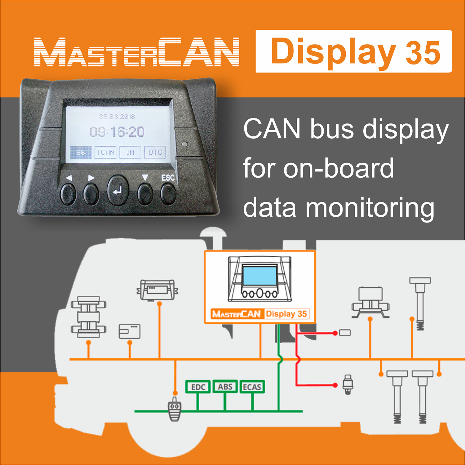
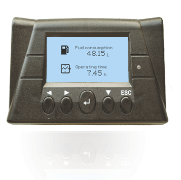
MasterCAN Display 35 – CAN bus display / HMI device designed for displaying CAN J1939 parameters and data from additional fuel level sensors, fuel flow meters, axle load sensors and other peripheral units used in vehicle telematics systems or stationary machinery monitoring system.
Parameters shown on the screen of CAN bus display can be selected from S6 database containing over 10,000 SPN (parameters) of machinery operation, used in CAN J1939, ISOBUS and CAN j1939/S6 Telematics Interface.
Core features of CAN J1939 display
- Displaying 402 parameters, selection from S6 Database‘s 10,000+ SPN,
- automatic CAN J1939/71 and ISOBUS messages scanning and parsing,
- possibility to parse and display proprietary CAN bus message,
- embedded converter of analog signal to CAN interface messages
- flexible configuration, adding/deleting screens, parameter and units naming
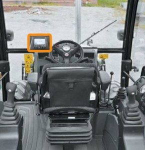
In vehicle telematics MasterCAN Display 35 is used as a dash mounted CAN display helping driver/machinery operator to monitor the most important engine (or other ECUs) operation parameters and to get readings from additional sensors and devices of tracking & monitoring systems (AVL) of construction equipment, agricultural machinery, railway vehicles, water transport, mining equipment and special vehicles for geological exploration and oil production, as well as in systems for remote monitoring of power (diesel) generator and boilers/burners sets.
Also, MasterCAN Display 35 can be employed for solving single tasks like: axle load display (i.e. on-board vehicle and/or semi-trailer axle load monitoring), fuel consumption monitoring system display or fuel tank monitor.
Vehicle manufacturers can consider including MasterCAN Display 35 as an optional “on request” equipment for providing their customer with additional possibility of on-board CAN bus parameters monitoring.
MasterCAN Display 35 features
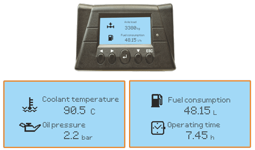
Flexible screen setting
Displaying up to 402 parameters, split into 21 group containing 20 parameters each. Flexibility of CAN J9139 display configuration includes: selecting to show 1 or 2 parameters per screen, uploading custom parameter icons, rename parameter or measuring units, add new screens in a group or remove screens from groups.
Industry-specialized models “Truck”, “Tractor” and “Marine” have preset screen groups for reducing efforts and time spent for configuration by installation technician.
Ready-made product, no SDK required
MasterCAN Display 35 is “out-of-the-box” product, which does not require further programming or user interface development, no HEX value calculations needed.
Configuration of MasterCAN Display 35 involves selecting network address of data source (engine, sensors, etc.), selecting from a drop-down list parameters to be shown on screens , adding/deleting screens, overlaying bit masks for detected proprietary CAN messages only (manual CAN bus parsing), renaming parameters or measuring units.
Automatic scanning and parsing CAN and ISOBUS
Over 10,000 parameters (SPN) described by J1939 (commercial vehicles) and ISOBUS (agricultural machines and equipment) are available to be shown on the screens of MasterCAN Display 35. After screen configuration, the display will automatically scan CAN bus and recognize available parameter groups (PGN).
The display can also show proprietary CAN J1939/71 messages, received from third-party developed devices with CAN-interface.
Unique technologies
CAN bus display in telematics system
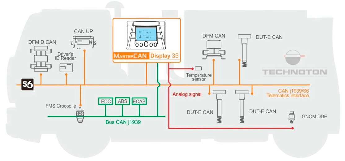
The following equipment for vehicle tracking/machinery telematics can be connected to MasterCAN Display 35:
- standard automotive (engine) CAN J939 and J1708 buses
- external equipment sending CAN J1939/71 messages
- 16 fuel level sensors
- 16 fuel flow meters
- 2 axle load sensors
- 42 senders with voltage/frequency/current/digital outputs (via DAC converter)
- telematics gateway or vehicle tracking device (AVL unit) with CAN bus interface
Examples of data on MasterCAN Display 35 screens
From standard CAN bus
- engine operation time, engine RPM;
- coolant and oil temperature, oil pressure;
- hydraulic system parameters and DTCs;
- air pressure in suspension system;
- gearbox parameters;
- parameters and condition of axles, drives, differential.
From CAN j1939/S6 interface
- fuel level, volume and temperature (from DUT-E fuel sensor);
- total engine fuel used and trip fuel consumption (from DFM fuel meter);
- fuel consumption by engine operation mode (from DFM flow meter);
- engine operation time total and split by operation mode (DFM).
From voltage/frequency senders
- axle load on truck and/or semi-trailer;
- engine RPM;
- coolant temperature.
U
Universal. Model with extended user rights for configuring screens. Displaying any of 10500+ operation parameters. Flexible adjustment of number of screens (21 groups, 10 screens in each).Configuration displayed parameters (1 or 2 on one screen, change parameter names and icons).
T
Tractor. Fuel level in tank, fuel Consumption, engine operating by CAN bus, machine hours. Preset screens (27 screens, two parameters on screen).
M
Vessel. Control of fuel in the tank, generator’s and boiler’s engine fuel consumption. Preset screens (37 screens, two parameters on screen).
G
Power supply voltage range, V
9 / 45
Maximal current consumption at supply voltage 12/24 V, mA, not more than
100 / 50
Temperature range, °C
-10 … +60
Ingress protection rating
IP40
LCD display
128×64 monochrome, with automatic light adjustment
Electromagnetic compatibility
ESD Protection, severity level II;
Electromagnetic interference protection, severity level IV.
Weight, kg, no more than
0,25
Digital interface
CAN j1939/S6

