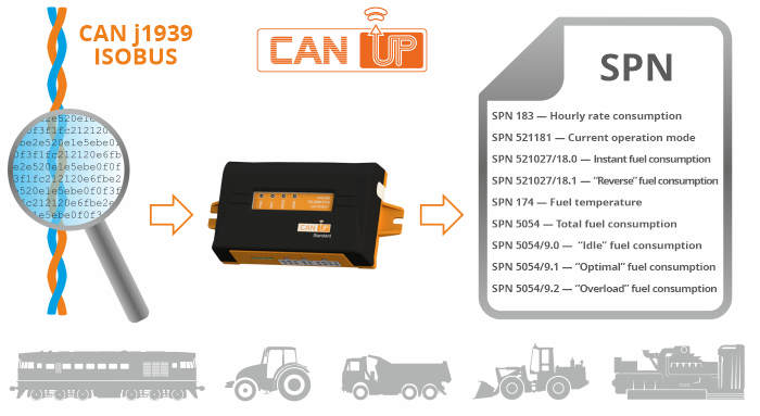
Automatic J1939 and ISOBUS scanning and parsing – one of the most important features of CANUp telematics gateway. The gateway is designed for advanced machinery telematics, which are characterized by many control points and number of standard data interfaces. Control points are – one or several engines and fuel tanks, auxiliary equipment and/or attached equipment. Standard data interfaces – e.g. CAN J1939, J1708, ISOBUS.
Nowadays it is quite difficult to find a GPS-tracker or vehicle telematics unit, which does not equipped with CAN J1939 interface. But different telematics boxes work differently with CAN bus data. And the automatic parsing of ISOBUS messages is almost impossible to find in the telematics market.
Benefits of automatic J1939 and ISOBUS scanning and parsing with CANUp
- Ability to obtain agricultural machinery-specific ISOBUS parameters
- Clear understanding of availability of required parameters in J1939/71 and ISOBUS
- Saving time when setting up on-board equipment and telematics server
- Elimination of errors that may occur during manual parsing of HEX format
- Available to telematics technicians of all skill levels
Reading data from vehicle data buses and interfaces
Modern machines are equipped with data buses, which gather data from standard vehicle sensors, electronic control units (ECU) and other vehicle electronics. There are several data bus standards used in commercial vehicles. The most common are SAE J1708 and SAE J1939, where you can find useful data for telematics, for example :
- FMS parameters: fuel level, total fuel used (calculated), engine RPM, coolant temperature, pressure and temperature of oil and other 0 altogether around 30 operation parameters.
- cab and outside temperature,
- ECU error codes (also called DTCs)
- vehicle specification,
- …and several thousands of others.
CANUp telematics gateway is designed to collect and analyze a large number of machinery operation parameters. Mainly, the parameters described by J1939/71 standard and ISOBUS agricultural machinery communication protocol, which is based on J1939.
What is ISOBUS?
ISOBUS – is a communication protocol based on SAE J1939 and CAN 2.0B used for agriculture vehicles. ISOBUS data bus can be found on various types of agricultural machinery and agricultural equipment. In addition to tractors and combines, ISOBUS is available on auxiliary and attached equipment – plows, seeders, cultivators, sprayers and others.
Why do you need to read data from ISOBUS? The data bus contains more than 7 thousand parameters of agricultural machinery operation: “classic” fuel consumption, engine speed, coolant temperature, as well as information about the settings and condition of trailed and attached equipment – immersion depth, seeding or spraying rate, etc.
The parameters are necessary for agricultural machinery telematics systems for recording the volume of agricultural work performed, as well as to assess the quality of the work.
Connecting to CAN bus
Despite the fact that some messages are available only when an active request is sent to a CAN bus, this method is not recommended, as it can interfere with the operation of the standard vehicle electronics and can lead to voiding factory warranty for a vehicle, which is especially critical for leased machinery.
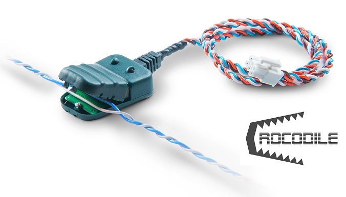
The safe way to connect is using Crocodile contactless CAN bus readers.
Crocodile reader leaves wire insulation intact and does not have direct electrical contact with the wires, thus remaining “invisible” to standard electronics and does not violate warranty for the equipment.

Automatic J1939/71 and ISOBUS scanner
One of the most popular approaches implemented in various vehicles telematics units and GPS trackers when it comes to CAN bus data – manual data parsing.
To simplify – when manually parsing CAN messages, telematics system technician applies masks to the “raw” messages of the CAN J1939 bus, coming in hexadecimal format (HEX). Thus, the installer “explains” to the telematics box which byte is responsible for which parameter. The disadvantage of this method is that the technician must have enough qualification and have experience in working with CAN bus.

There are two ways to search for the required parameter (SPN) when configuring Onboard Reports in CANUp gateway:
- manual filter by SPN number or name. To do this, you need to know what to look for. If the installer needs to select a parameter of one of the Technoton telematics equipment – all message description for all sensor can be found in Operation Manuals.
- run automatic scanner of J1939/71 parameters.
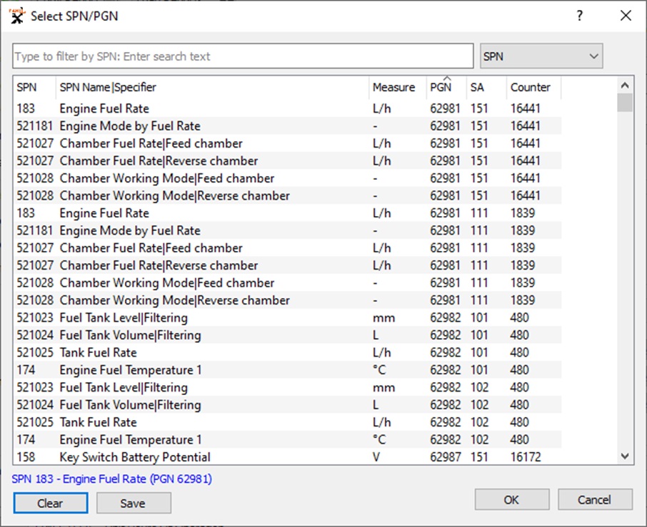
The screenshot of CANUp service software above shows the work of J1939 and ISOBUS automatic scanner. The scanner allows you to view all available parameters (SPN) and their groups (PGN):
- SPN (first column) – contains the parameter number. The number is unique, there are no two different parameters with the same number. Descriptions of over 10,000 parameters (SPN) can be found in S6 Database. However, two different data sources (SA) can send the same parameter. For example, if a vehicle has two fuel tanks in which two fuel level sensors are installed.
- SPN name – contains a descriptive name of the parameter and its specifier. Specifier – specified description of a parameter, for example, “Fuel consumption in the return” and “Fuel consumption in the supply” have the same SPN number, but differ due to the specifier.
- Measure is a qualifying column indicating units of measurement that helps a technician to find correct data.
- PGN is the number of the message, which contains the parameter (SPN).
- SA – network address of the data source, e.g. additional (level sensor, fuel flow meter, etc.) or standard ECU.
Sending J1939 and ISOBUS parameters to telematics server

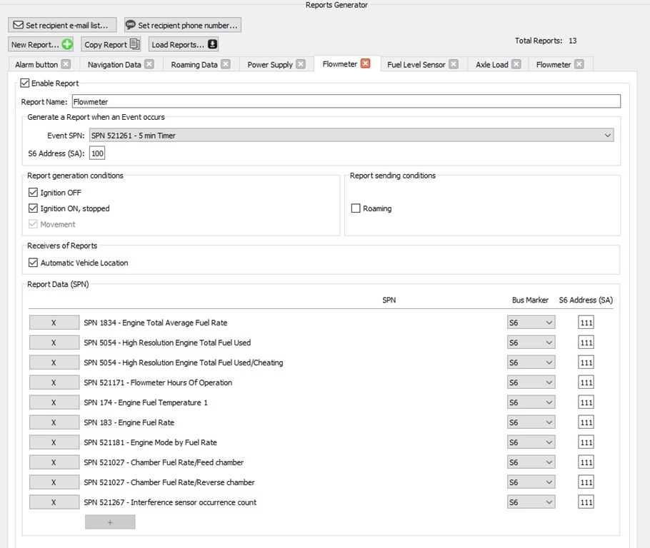
CANUp allows configuring 20 Onboard Reports, 10 parameters each. When configuring Onboard Reports, you can select generation conditions, for example, “timer 1 minute” or triggering Event “Fuel drain”. In addition, a telematics technician can define the transmission conditions and data recipients – a telematics or vehicle tracking server, email addresses and phone numbers of users (to send SMS notifications about Event detection bypassing the server).
In addition, there are some additional conditions for generating of Onboard Reports possible: for instance, presence/absence of movement, external power supply ON/OFF. Also, it is possible to select the queue for sending reports – in chronological order (FIFO) or “fresh first” (LIFO).
