Translation of original article
Author: Viktor Panasyuk, Technical Department Head, Technoton.
Fuel flow meters are used in telematics for about 20 years. Initially, they were manufactured with pulse output only.
How does flow meter with pulse output works? When fuel passes through a flow meter, an electrical pulse is formed. One pulse corresponds to fuel consumption, which is equal to the volume of flow meter’s measuring chamber. That’s simple.
But simplicity is the only advantage of such design. There are much more disadvantages.
There are special requirements to telematics unit, which will receive signal from flow meter and send in to a telematics server.
The telematics unit should have an input that recognizes and counts pulses, i.e. a pusle counter. Pulse counter should have high bit depth to avoid signal overflow. Next step – recalculate counted pulses into liters.
Telematics service should process received data, “decompose” consumed fuel data according to time stamps and provide users with information in table format. Not all telematics services are able to do that.
Thus, even with a perfectly working flow meter, quite often a user cannot get the most important information – hourly fuel consumption (also called instant fuel consumption).
Fuel flow meters with a pulse output additionally have some limitations in its design.
- flow meter does not send diagnostic information on its condition and operation.
- fuel consumption data is lost when signal cable is disconnected. Some models of DFM flowmeters can partially restore it after reconnecting to telematics unit. But this process takes time, during which new information will not be received.
- it is impossible to obtain online information about flowmeter tampering with air or interfering into flowmeter’s operation with magnetic field. Some models of DFM flowmeters save these data in internal memory. However, to view the data, you must directly connect the flow meter to PC.
- Pulse output is sensitive to power surges in the network. Consumption data can be greatly distorted.
- A malefactor can put a “fuse” on signal cable on the sly. This simple device will “toss” additional “fake” fuel consumption, and it will be very difficult to find it out.
- If you need to monitor two or more engines – two or more flow meters are installed respectively. To process data, you need a telematics unit with several pulse inputs, or you’ll need several telematics units. Fuel monitoring system becomes complicated, its cost grows, and reliability of operation decreases.
All these issues are not applicable for DFM fuel flow meters with digital interface.

Processor of such flow meter converts pulses into a digital format. Information on fuel consumption is processed “on board” of the flow meter and stored in its non-volatile memory.
Thanks to special mathematical algorithms, digital communication channels are much better protected, than analog ones. There is no loss or distortion of information from DFM flow meter with digital interface.
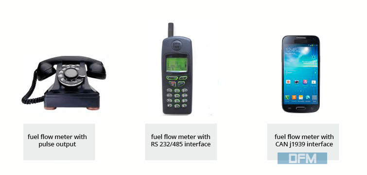
For instance, compare capabilities of old wired telephone with a dial plate and a modern smartphone.
Advantages of DFM fuel flow meters with digital interfaces:
- A user simultaneously receives variety of parameters describing fuel consumption and engine performance of vehicle.
- Data on total fuel consumption is transmitted in finalized format, with an accuracy of one milliliter. This counter is not resettable and is incremented over the life of the DFM.
- User receives data on engine operation time with the accuracy to 1 second. This counter is also constantly incremented.
- User has access to detailed information on machinery operation in various modes (idle, normal, overload). It allows to carry out detailed analysis of machinery operation, thus achieving the most efficient operation.
- DFM sends several diagnostic parameters. They allow remote detection of tampering and interference attempts, identify failures in DFM’s operation and malfunctions of fuel system. This allows to normalize operation of both the flow meter and the vehicle with minimal time and effort.
- Easy fuel monitoring of complex objects. Multiple DFM with digital interface can be connected to one digital (RS-485 or CAN) port of telematics unit. No need to spend money for additional unit, monitoring system remains simple and reliable in operation.
There are several types of digital interfaces. The most promising from vehicle telematics point of view is CAN j1939 interface. It is the absolute leader in practical speed, reliability, ease of scaling and ease of integration.

Comparison table for flowmeters with digital CAN interface and pulse output.
CAN interface
Pulse output
Output data set
- Fuel consumption counter – accuracy 0.001 L
- Operation hours counter- 1s accuracy
- Instant consumption – accuracy 0.05 l / h
- Operation mode
- Temperature
- Active errors – IDs, quantity
- Saved errors – quantity
- Flow Rate in Feed line – accuracy 0.05 L/ h
- Flow Rate in Return line- accuracy 0.05 L / h
- Interference time – 1s accuracy
- Tampering volume – accuracy 0.001 L
… more than 30 parameters
Pulses – with the step equal to chamber volume, i.e. from 5 to 20 ml
Accuracy
1%
1-2%
Selfdiagnostics
Yes
No
Sending data on interference with magnetic field and/or tampering
Yes
Yes
No
Interruption in data sending or loss of intermediate data
Not critical
No
Using two and more flowmeters on one object
Yes, within one network. Up to 8 units through CAN j1939/S6 interface, data from standard CANbus can be incorporated too
Each flow meter to a separate pulse input or telematics unit
